Published: June 30, 2025 | Updated: July 31, 2026
FLOATING WIND
Floating wind has no shortage of platform designs. An independent assessment commissioned by the UK’s Technology Leadership Board scored 117 floating concepts against 39 weighted criteria and shortlisted 15 for a hypothetical 750 MW North Sea project. The finding that matters most is not the ranking. On the assessment’s own definition, tied to a commercial wind farm of 100 MW or more, no floating or hybrid concept anywhere has reached TRL 8 or 9. The highest maturity achieved in the field is TRL 7. That is uncomfortable for a sector planning gigawatt pipelines, and it reframes what platform selection is: not a question settled by hydrodynamics, but by which yard can fabricate the hull, which vessel can install it, and which lender will accept the residual technology risk.
👉 Floating Offshore Wind in Japan: Market Structure, Costs, and Policy
→
Execution Reality
→
Bankability Test
The TLB assessment tracked 117 floating concepts, but on OpenWater’s definition no floating or hybrid unit anywhere has reached TRL 8 or 9, the levels tied to a commercial wind farm of 100 MW or more. The binding constraint is not a shortage of designs. It is the absence of designs proven at commercial scale, which is precisely what lenders price.
Across the main archetypes the same assessment found a spread of roughly 15% in indicative project CAPEX. No archetype delivers a step change on cost alone, so selection turns on fabrication fit, installation method, and risk transfer rather than a headline cost advantage.
Deep-draft spars were kept off the shortlist for lack of a suitable UK construction port. Hybrid concepts, which are bottom-fixed designs stretched into deep water, are held to about 80 m because no jack-up vessel can install a turbine deeper than that. Platform choice is an infrastructure decision as much as a naval architecture one.
What Floating Platform Design Must Solve
A fixed-bottom turbine transfers loads directly into the seabed through a monopile or jacket foundation. Beyond roughly 50 to 60 meters of water depth, the structural mass and cost of doing this become prohibitive. A floating platform replaces that fixed connection with a buoyant structure held by mooring lines, which introduces a different problem: the platform moves, and the motion must stay controlled enough for the turbine to operate safely across a design life of at least 20 years (the ClassNK minimum, or the turbine’s rated life if longer). Nacelles and blades are not built for large or rapid angular motion. Tilt beyond a few degrees changes the rotor thrust vector, increases fatigue, and degrades yield. Every floating design is one answer to the same question: how to hold tilt, pitch, and heave inside the turbine’s tolerance under combined wind, wave, and current loading, in a specific sea environment, for 20 years.
Stability and motion response
A floating body is statically stable when its center of gravity sits below its center of buoyancy, or when the waterplane area (the cross-section at the water surface) generates enough righting moment as the structure tilts. The archetypes differ in which mechanism they lean on: ballast for spar, waterplane area for semi-submersible and barge, forced buoyancy under tension for TLP. Static stability is necessary but not sufficient, because waves, gusts, and current drive oscillation in six degrees of freedom. Designers run coupled time-domain simulations across hundreds of load cases, including 50-year and 100-year return period extremes, to keep motion within the turbine’s design envelope and mooring loads within safe limits.
Mooring systems
ClassNK’s FOWT guidelines (NKRE-GL-FOWT01) recognize two broad categories. Multi-point catenary systems use sagging lines that generate restoring force through their own weight, allowing more horizontal movement but tolerating depth variation well. Tension-leg systems use taut near-vertical tendons under pre-tension, which minimizes vertical motion but demands precise seabed anchoring and is more sensitive to depth change. Mooring is not separable from platform type: spars and semi-submersibles typically use catenary or semi-taut moorings, while TLPs are defined by their tendons. The mooring system in turn sets the anchor type (drag anchors, suction piles, or driven piles), each with its own seabed requirements and installation cost profile.
The Four Main Platform Types
ClassNK’s FOWT01 framework (Table 1-2) formally recognizes five floating platform categories: semi-submersible, barge, spar, tension-leg platform (TLP), and “other.” In practice, the first four define the design space for commercial-scale development.
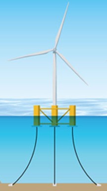
Semi-Submersible
A semi-submersible carries the turbine tower on a surface deck supported by vertical columns that extend below the waterline into submerged pontoons. Operating partially submerged reduces its waterplane area, which dampens wave-induced motion relative to a surface vessel of equivalent displacement.
Water depth: roughly 50 to 300+ m, with the upper limit set by mooring choice.
Advantage: Fabrication-friendly geometry buildable in a drydock, supports large turbine classes, and can be towed to site with a standard anchor-handling vessel.
Constraint: More complex to fabricate than a spar or barge, and its larger waterplane area means more wave-frequency motion than a spar.
Spar
A spar is a tall, narrow cylindrical hull extending 80 to 120 meters below the surface with heavy ballast at the bottom. Placing most of its displacement far below the wave-active zone pushes its natural roll and pitch periods well beyond the dominant wave range, which minimizes resonant excitation without relying on waterplane geometry.
Water depth: generally 100 m or deeper, and best suited beyond 200 m where the long hull is fully submerged.
Advantage: The lowest wave-induced motion of any type, and proven in service (Hywind Scotland, commissioned 2017, remains the world’s first commercial floating wind farm).
Constraint: Cannot be installed in shallow water, requires a large specialized crane vessel for turbine mating, and is difficult to fabricate in most Asian yards, which are optimized for wider, shallower structures.
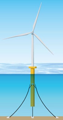
Spar installation requires a heavy-lift vessel capable of upending a 100+ meter hull offshore before the turbine can be mated. No vessel currently based in Japan can perform this operation. Any spar-type project in Japanese waters would depend on mobilizing a specialized crane vessel from Europe or the US Gulf, adding significant schedule risk and mobilization cost. The UK faces a parallel constraint on the port side. Until this vessel and port class exists regionally, spar remains structurally disadvantaged relative to semi-submersible regardless of its motion performance.
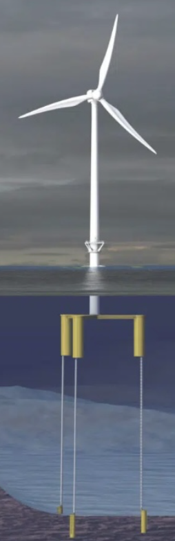
Tension-Leg Platform (TLP)
A TLP is a buoyant platform held down by high-tension vertical tendons anchored to the seabed. Tendon tension balances the hull’s excess buoyancy, which virtually eliminates vertical motion while allowing limited horizontal movement. For a given sea state it delivers the lowest dynamic motion of any design, which is attractive for energy yield.
Water depth: roughly 50 to 200+ m, and one of the few designs still viable at 50 to 80 m where semi-subs become oversized.
Advantage: Minimal vertical and angular motion, a compact deck footprint, and potentially lower material cost than a semi-sub for the same turbine class.
Constraint: Tendon installation demands precise seabed anchoring, tolerance for depth variation is low, and the commercial-scale track record in wind applications remains limited.
Barge
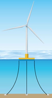
A barge is a flat-bottomed, wide-beam hull that gains stability from its large waterplane area rather than ballast depth or mooring pre-tension. Barges can be built in conventional shipyards without specialized dry-dock equipment, making them the most accessible type from a manufacturing standpoint.
Water depth: generally 50 to 100 m, limited by the mooring system in deeper water.
Advantage: The lowest fabrication complexity and the widest range of compatible yards, and it can be outfitted onshore and towed out.
Constraint: The large waterplane area produces significant wave-frequency motion, so damping measures such as bilge keels are needed to hold turbine tilt within limits, which makes it less attractive in high-energy wave environments.
Platform Comparison
| Platform type | Primary stability mechanism | Indicative water depth | Motion performance | Fabrication complexity |
|---|---|---|---|---|
| Semi-submersible | Waterplane area + ballast | 50 to 300+ m | Moderate | High |
| Spar | Deep ballast | 100 to 300+ m | Best | Very high |
| TLP | Tendon tension (forced buoyancy) | 50 to 200+ m | Best (vertical) | Moderate |
| Barge | Wide waterplane area | 50 to 100 m | Lowest | Low |
117 Concepts Assessed, and Only Three Proven Offshore
Most platform screening is done privately by developers and never published. The assessment released in June 2026 by OpenWater Renewables for the UK’s Technology Leadership Board is an exception, and it is useful because it applies one consistent method across the whole field rather than defending a single design.
At a data cut-off of 28 February 2026 the study’s database held 117 floating concepts plus six hybrid concepts, the latter being fixed-bottom designs adapted for deep water. Each was scored against 39 technical, commercial, and delivery criteria, weighted by their effect on levelized cost and on the project risk profile. The reference case was a hypothetical 750 MW wind farm off Scotland in 100 to 150 m water depth, using 15 MW turbines and operating between 2030 and 2035. Fifteen concepts made the shortlist: eight steel, six concrete, and one hybrid pairing a concrete float with a steel turret mooring. Six of the 2025 shortlist were displaced, which suggests a field still reordering rather than consolidating.
The most consequential finding is about maturity rather than ranking. Technology readiness is measured on a TRL scale, and OpenWater defines TRL 8 and 9 against a commercial wind farm of 100 MW or more. On that definition, no floating or hybrid unit anywhere has reached TRL 8 or 9. The highest maturity achieved in the field is TRL 7.
The distribution underneath that ceiling is thin. Most tracked concepts sit at TRL 3 or 4, verified by numerical simulation and tank testing. Twenty-seven have advanced to TRL 5. Only 15 have reached TRL 6 or above, which requires at least one prototype or demonstrator of 1 MW or more operating offshore, and those 15 break down as eight semi-submersibles, four spars, two barges, and one TLP. Within the separate 15-concept North Sea shortlist, only three sit at TRL 6 or 7. The recommendation follows directly: select a concept that has reached at least TRL 7 by final investment decision.
Japan appears in this data in a way that deserves attention. Three of the concepts that reached TRL 6 or 7 came from the Fukushima FORWARD demonstration: JMU’s Advanced Spar at TRL 7, Mitsui’s Compact Semi-sub at TRL 7, and MHI’s V-shaped Semi-sub at TRL 6. All three have since been removed and their development has ended. Japan therefore holds a meaningful share of the world’s demonstrated floating experience in projects that no longer exist, which is a different position from having none at all, and a harder one to convert into a bankable reference.
Set against a global pipeline that assumes gigawatt-scale floating deployment from the early 2030s, that is a narrow base, and it reframes what choosing a platform actually means. For a first commercial project the realistic choice set is not 117 concepts, and arguably not even 15. One caveat on weighting: OpenWater describes the exercise as limited and qualitative in scope, and the conclusions are its own rather than an industry standard.
TRL is where engineering maturity converts into financing terms. Lenders underwrite P90 energy yield, and a concept without full-scale operating data forces a wider P50 to P90 spread, which lowers the debt service coverage ratio at any given gearing. A design at TRL 5 does not simply carry more technical risk; it carries a documented absence of the operating record lenders use to narrow that spread. This is why a recommendation to reach TRL 7 by FID is a financing statement rather than an engineering preference, and why novel concepts, including hybrid TLP designs, face a lender acceptance gap that established semi-submersibles do not.
Platform Cost Compared: A 15% Spread, Not a Breakthrough
The assessment also produced an indicative CAPEX comparison across archetypes, expressed as approximate whole-project cost relative to a concrete barge baseline.
| Archetype | Indicative project CAPEX (concrete barge = 100%) |
|---|---|
| Concrete barge | 100% |
| Concrete semi-submersible | 100% |
| Hybrid guyed tower | 95 to 100% |
| Steel and concrete hybrid barge | 110% |
| Steel semi-submersible | 105 to 115% |
The spread across the whole set is roughly 15%. That is a meaningful margin on a multi-billion dollar project, but it is not the order-of-magnitude difference the platform debate sometimes implies. No archetype wins on cost alone, which pushes the decision back onto fabrication capability, installation method, and who carries the technology risk.
Two cautions apply to reading these figures. They describe a North Sea case with a UK supply chain, so they cannot be used as an absolute cost benchmark for Japan, where the Japan Wind Power Association’s fixed-bottom CAPEX reference of about 908,000 JPY/kW already sits well above global comparators. And the claimed cost advantage of hybrid concepts depends in part on future investment in automated fabrication and deep-water installation vessels that has not yet been committed, a caveat the assessment itself flags.
👉 Offshore Wind Cost Structure and Economics: What Drives LCOE
Why Ports and Installation Vessels Eliminate Designs First
The most transferable lesson is about what removed concepts from contention, and in this assessment the reasons are mostly infrastructural rather than hydrodynamic. Deep-draft spars were excluded because no UK construction port can handle them. Hybrid concepts stayed off the top 15 largely on O&M scores: the depths at which they can currently be deployed are limited, they cannot be towed back to port for major repair, and there are too few vessels suited to repairing them offshore. TLPs also dropped out of the shortlist, though the report gives two different accounts of why, citing installation complexity in North Sea conditions in its conclusions and, in the body, displacement to 24th place by newer semi-submersible and barge concepts.
The clearest case is the hybrid category, and it is worth being precise about what it is. Hybrids are not floating platforms. They are bottom-fixed structures, anchored at the base like a monopile, then reinforced with guy wires, buoyancy, or an articulated joint so they can reach depths normally reserved for floating. On paper they work to 120 or 130 metres, in some cases 200. In practice the assessment holds them to about 80 metres, because no jack-up vessel exists that can install a turbine deeper than that, and the alternative of a very large semi-submersible crane vessel is expected to be expensive and exposed to weather downtime. The ceiling is not in the design. It is in the fleet available to erect it.
This is also where the distinction between platform families becomes commercially concrete. Floating platforms are assembled quayside and towed out complete, which is much of their economic rationale, so the jack-up ceiling does not bind them. Bottom-fixed and hybrid designs must have the turbine erected on site. Two families, the same water depth, entirely different vessel dependencies.
Japan has arrived at the same layer from the opposite direction. In July 2026 its Ports and Harbours Bureau selected seven research projects to establish offshore construction methods for floating wind, covering cranes, seabed drilling, mooring, anchoring, weather-window forecasting, an offshore work base, and base-port scheduling, six of them running to FY2028. Not one addresses the turbine. Dedicated installation and tow-out vessels sit in a separate shipbuilding track and were not in that package either. Two independent exercises, one British and one Japanese, arrive at the same place: what decides a floating project is the layer below the platform.
👉 Japan Funds Floating Wind Installation R&D: Seven MLIT Projects, and the Vessel Question
Installation capability, not platform selection, may set the earliest credible date for commercial deployment at scale, and the dependency differs sharply by family. A hybrid concept is capped near 80 m by the jack-up fleet. A spar needs an offshore heavy-lift crane vessel to upend and mate. A semi-submersible or barge needs quay length, draft, and tow-out weather windows instead. Developers evaluating platform options should consider testing each shortlisted concept against the installation spread actually contractable in their region and window, rather than the spread assumed in the concept’s own cost case.
Japan’s Platform Strategy: Where the Pipeline Points
Japan applies the same constraints to a different industrial base and reaches a narrower answer. At the end of 2025 it had 5 MW of operational floating capacity, the smallest installed base among the seven countries with floating wind online (GWEC, 2026), and the 16.8 MW Goto project, winner of Japan’s first floating auction in 2021, was commissioned in early 2026. These milestones matter less for the energy they produce than for the supply chain and installation knowledge they generate.
The NEDO Green Innovation Fund Phase 2 demonstrations are the more significant near-term indicator. The Akita south coast project, led by a Marubeni consortium including JMU, Toa Construction, Tokyo Steel Rope, Kansai Plant, and JFE Engineering, targets roughly 400 m water depth with 12 to 15 MW turbines and a commissioning target of October 2029, with a second project off Aichi providing a parallel data set. At 400 m, semi-submersible is effectively the only technically mature option, which makes the choice close to predetermined. The industrial logic is explicit in the METI Industrial Vision (2nd edition): Japan’s shipbuilding and heavy fabrication base can mass-produce large steel hulls in a way few countries can replicate. EEZ expansion reinforces the same direction, since most eligible sites sit well beyond 200 m, ruling out barge and constraining TLP.
Japan’s most interesting divergence from the TLB shortlist is the TLP. In May 2026 Obayashi Corporation received an Approval in Principle from ClassNK for the support structure of a TLP that is hybrid in its materials rather than its geometry: steel and concrete members fabricated separately, then joined at an assembly yard on site. ClassNK describes this as the first AiP it has issued for a steel and concrete hybrid TLP support structure. Obayashi’s own estimate puts the saving at 25% of floater construction cost against a steel semi-submersible, and it argues the tight mooring footprint limits the sea area occupied and therefore the effect on fishing.
That is a fabrication argument more than a hydrodynamic one, which is exactly the axis on which the TLB assessment turned. The TLB set TLPs aside for installation complexity in North Sea conditions, but a design whose parts can be made in separate plants and assembled near the site is answering a different constraint. The work sits within a NEDO programme, with a sea trial carrying a turbine targeted for 2028. Whether it becomes Japan-developed intellectual property depends on reaching that full-scale reference, not on the AiP.
👉 From Demonstration to Commercialization: Floating Offshore Wind Case Studies
Platform choice is a supply chain commitment, not just an engineering decision.
The TLB assessment is most useful for what it removes rather than what it ranks. Spar and TLP left the shortlist on ports and installation sequencing while scoring well on motion. That is the clearest available statement that floating wind selection has moved out of naval architecture and into industrial capability, and it is the same conclusion Japan reached from the opposite direction when it concentrated demonstration funding on semi-submersibles its own yards can build.
The maturity finding deserves more attention than it has had. If only three shortlisted concepts have been proven offshore and none at commercial scale, the sector’s pipeline arithmetic rests on designs that have not yet earned the operating record their financing will require. Concept proliferation has generally been read as healthy competition. It can equally be read as a field that has not yet converged enough for anyone to build the fabrication and installation base that would make one design cheap.
For Japan the practical question is not which archetype is best in the abstract. It is whether the installation and port layer matures on the same schedule as the platform layer. Two independent assessments now point at the same missing asset, and neither country has funded it yet.
Related DeepWind Articles
- Floating Offshore Wind in Japan: Market Structure, Costs, and Policy Framework
- Japan Funds Floating Wind Installation R&D: Seven MLIT Projects, and the Vessel Question
- From Demonstration to Commercialization: Floating Offshore Wind Case Studies
- Post-2030 Floating Offshore Wind: Technology Trends and Market Outlook
DeepWind Weekly tracks Japan’s offshore wind market beyond headline announcements, focusing on execution risk, cost structure, project viability, supply-chain constraints, and policy implications.
Subscribe to receive weekly intelligence on Japan’s offshore wind market.
Why Isn't Floating Wind Bankable in Japan Yet?
The synchronized supply-chain bottleneck, quantified node by node, with a full sensitivity ranking and a bankability ladder of scaling conditions. Includes Simulator Professional (β) access to reproduce every figure on your own assumptions.
See the full analysis →