Published: June 30, 2025
Last updated: June 14, 2026
FLOATING WIND
Japan’s 2030 floating wind pipeline has converged on semi-submersible. With the 16.8 MW Goto project commissioned in early 2026 and NEDO’s Phase 2 demonstrations targeting commercialization-ready technology by 2030, Japan has made a de facto platform choice — driven as much by fabrication infrastructure as by engineering merit. Of the four main types recognized under Japan’s regulatory framework (ClassNK FOWT01) — semi-submersible, spar, TLP, and barge — only semi-submersibles can be built in Japanese yards at scale, installed without heavy-lift capacity unavailable in Japan, and underwritten by project lenders at current risk appetite. This article explains how each type works, where they differ, and why Japan’s pipeline signals matter for developers, suppliers, and investors planning beyond 2030.
👉 Floating Offshore Wind in Japan: Market Structure, Costs, and Policy
→
Execution Reality
→
Bankability Test
Semi-submersible, spar, TLP, and barge are the four platform types recognized under Japan’s regulatory framework (ClassNK FOWT01). Semi-submersibles currently account for the majority of global deployments and are the design around which Japan’s demonstration pipeline is organized.
Water depth, fabrication port capability, installation vessel type, and mooring system are all coupled to platform geometry. A country that commits early to one platform type builds a matching industrial base — and faces switching costs if it changes course later.
At the end of 2025, Japan had 5 MW of operational floating wind. The 16.8 MW Goto project commissioned in early 2026. NEDO’s Phase 2 demonstrations target commercialization-ready technology by 2030. Policy and execution must accelerate in parallel with the engineering.
What Floating Platform Design Must Solve
A fixed-bottom offshore wind turbine transfers loads directly into the seabed through a monopile or jacket foundation. At depths beyond roughly 50–60 meters, the structural mass and cost of doing this become prohibitive. A floating platform replaces the fixed connection with a buoyant structure held in position by a mooring system — but introduces a new set of engineering problems: the platform moves, and that motion must be controlled precisely enough that the turbine above it can operate safely for a design life of at least 20 years (the minimum required under ClassNK guidelines, or the turbine’s rated design life if longer).
The fundamental constraint is that turbine nacelles and blades are not designed for large or rapid angular motions. Platform tilt beyond a few degrees changes the rotor thrust vector, increases structural fatigue, and degrades energy yield. Every floating platform design is ultimately an answer to one question: how do we keep tilt, pitch, and heave within acceptable limits under the combined loads of wind, waves, and current — across a 20-year service life in a specific sea environment?
Engineering Fundamentals: Stability, Mooring, and Load Management
Static stability
A floating body is statically stable when its center of gravity (CoG) lies below its center of buoyancy (CoB) — or when the geometry of the waterplane area creates a sufficient righting moment if the structure tilts. Platform designers achieve this through ballast (dense materials placed low in the structure), hull geometry (wide waterplane area that resists tilt), or both. The three main approaches each exploit a different primary mechanism: ballast (spar), waterplane area (semi-submersible and barge), or forced buoyancy under tension (TLP).
Dynamic stability and motion response
Static stability is necessary but not sufficient. Waves, wind gusts, and current create dynamic loads that cause the platform to oscillate in six degrees of freedom (surge, sway, heave, roll, pitch, yaw). Designers use coupled time-domain simulations to predict platform motions under site-specific environmental loading across hundreds of load cases — including extreme 50-year and 100-year return period events. The objective is to keep motions within the turbine’s design envelope and ensure mooring loads remain within safe limits.
Mooring systems
ClassNK’s FOWT guidelines (NKRE-GL-FOWT01) classify mooring systems into two broad categories: multi-point catenary mooring systems (SMS-CM), where mooring lines form sagging curves and generate restoring force through their own weight; and tension-leg mooring systems, where taut vertical or near-vertical tendons generate restoring force through their pre-tension. Catenary systems allow more horizontal movement but are more tolerant of depth variation. Tension-leg systems minimize vertical motion but require precise seabed anchoring and are more sensitive to water depth changes.
Mooring choice is not separable from platform type. Spar and semi-submersible platforms typically use catenary or semi-taut moorings. TLPs are defined by their tensioned tendons. The mooring system also determines anchor type — drag anchors, suction piles, or driven piles — each with different seabed condition requirements and installation cost profiles.
The Four Main Platform Types
Japan’s regulatory framework (ClassNK FOWT01, Table 1-2) formally recognizes five floating platform categories: semi-submersible, barge, spar, tension-leg platform (TLP), and “other.” In practice, the first four define the design space for commercial-scale development.
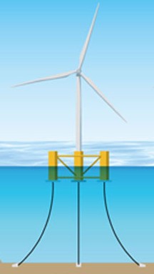
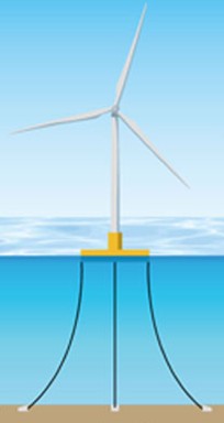
Semi-Submersible
A semi-submersible platform consists of a surface deck carrying the turbine tower, supported by multiple vertical columns that extend below the waterline and connect to submerged pontoons or lower hulls via bracings. By operating in a partially submerged state, the platform reduces its waterplane area — the cross-sectional area at the water surface — which dampens wave-induced motion compared to a surface vessel of equivalent displacement.
Water depth range: approximately 50–300+ meters, though upper limits depend on mooring system choice.
Key advantage: Fabrication-friendly geometry (can be built in a drydock or graving dock), able to support large turbine classes, can be towed to site with a standard anchor-handling vessel.
Key constraint: More complex fabrication than a spar or barge; larger waterplane area than a spar means greater wave-frequency motion response.
Japan relevance: The dominant design in Japan’s demonstration pipeline. The NEDO Green Innovation Fund Phase 2 demonstration at Akita south (Marubeni lead consortium, target water depth ~400 m, 12–15 MW class, commissioning target October 2029) uses a semi-submersible concept. Japan’s shipbuilding industry — including JMU and JFE Engineering — has the fabrication capability to produce semi-sub structures at scale.
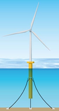
Spar
A spar is a tall, narrow cylindrical hull that extends deep below the surface — typically 80–120 meters — with heavy ballast at the bottom. By placing most of its displacement far below the wave-active zone, the spar achieves excellent pitch and roll stability without relying on waterplane area geometry. The platform’s natural roll and pitch periods are pushed well beyond the dominant wave period range, minimizing resonant excitation.
Water depth range: generally 100 meters or deeper; best suited to very deep water (200+ m) where the long hull can be fully submerged.
Key advantage: Lowest wave-induced motion of any platform type; proven technology (Hywind Scotland, commissioned 2017, remains the world’s first commercial floating wind farm).
Key constraint: Cannot be installed in shallow water (the hull must be submerged before turbine installation); requires a large, specialized offshore crane vessel for turbine mating; difficult to fabricate in most Asian shipyards, which are optimized for wider, shallower structures.
Japan relevance: Less favored in Japan’s near-term pipeline. Japan Sea and Pacific coast depths are suitable, but the lack of local heavy-lift vessel capacity and the assembly logistics challenge make spar less competitive than semi-sub for Japan’s 2030 demonstration phase.
Spar installation requires a heavy-lift vessel capable of upending a 100+ meter hull offshore before the turbine can be mated — an operation that no vessel currently based in Japan can perform. Any spar-type project in Japanese waters would depend on mobilizing a specialized crane vessel from Europe or the US Gulf, adding significant schedule risk and mobilization cost. Until Japan or a neighboring country invests in this vessel class, spar remains structurally disadvantaged relative to semi-submersible for domestic deployment.
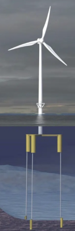
Tension-Leg Platform (TLP)
A TLP is a buoyant platform held down by high-tension vertical tendons anchored to the seabed. The excess buoyancy in the hull is balanced by the tendon tension, which virtually eliminates vertical motion (heave, pitch, roll) while allowing limited horizontal movement. The result is a platform with the lowest dynamic motion of any design for a given sea state — making it attractive for maximizing turbine energy yield.
Water depth range: approximately 50–200+ meters; one of the few designs that remains viable at relatively shallow depths (50–80 m) where semi-subs become oversized.
Key advantage: Minimal vertical and angular motion, compact deck footprint, potentially lower material cost than semi-sub for equivalent turbine class.
Key constraint: Tendon installation requires precise seabed anchoring; less tolerant of water depth variation; relatively limited operational track record at commercial scale for wind applications.
Japan relevance: Active R&D interest. In 2025, Obayashi Corporation received an Approval in Principle (AiP) from ClassNK for a hybrid TLP design — combining TLP and semi-sub concepts — aimed at reducing motion while retaining fabrication flexibility. If commercialized, this could become Japan-developed IP in a segment where no country currently dominates at scale.
Hybrid or novel platform concepts — including the Obayashi TLP hybrid — face a lender acceptance gap that pure semi-submersibles do not. ClassNK’s AiP is necessary but not sufficient: project finance lenders require at least one full-scale installation reference before underwriting. Semi-submersibles with established motion data from comparable sites allow lenders to model P90 energy yield with higher confidence, narrowing the P50–P90 spread in the DSCR calculation. Design standardization around semi-submersible is the most direct path toward DSCR ≥1.35x under current lender risk appetite — hybrid TLP designs are unlikely to be financeable in Japan before the early 2030s at earliest.
Barge
A barge-type platform is a flat-bottomed, wide-beam hull that achieves stability through its large waterplane area rather than through ballast depth or mooring pre-tension. Barges can be fabricated in conventional shipyards without specialized dry-dock equipment, making them the most accessible platform type from a manufacturing standpoint.
Water depth range: generally 50–100 meters, limited by the mooring system in deeper water.
Key advantage: Lowest fabrication complexity, widest range of compatible shipyards, can be outfitted onshore and towed to site.
Key constraint: Large waterplane area creates significant wave-frequency motion response; requires active damping systems (e.g., bilge keels, motion dampers) to keep turbine tilt within acceptable limits; less attractive for high-energy wave environments such as Japan’s Pacific coast.
Japan relevance: Potential fit for protected or moderate-wave sites, but Japan’s dominant sea environments — North Sea analogue conditions on the Japan Sea coast, typhoon exposure on the Pacific side — tend to favor designs with better motion performance.
Platform Comparison
| Platform type | Primary stability mechanism | Indicative water depth | Motion performance | Fabrication complexity | Japan pipeline status |
|---|---|---|---|---|---|
| Semi-submersible | Waterplane area + ballast | 50–300+ m | Moderate | High | Leading (NEDO Phase 2 demos) |
| Spar | Deep ballast | 100–300+ m | Best | Very high | No near-term project |
| TLP | Tendon tension (forced buoyancy) | 50–200+ m | Best (vertical) | Moderate | R&D stage (Obayashi AiP) |
| Barge | Wide waterplane area | 50–100 m | Lowest | Low | No near-term project |
Japan’s Platform Strategy: Where the Pipeline Points
At the end of 2025, Japan had 5 MW of operational floating offshore wind capacity — the smallest installed base among the seven countries with floating wind online globally (GWEC, 2026). The 16.8 MW Goto offshore wind project, winner of Japan’s first floating wind auction in 2021, completed turbine installation before the end of 2025 and achieved commissioning in early 2026. These milestones matter less for the energy they produce than for the supply chain and installation knowledge they generate.
The more significant near-term indicators are the NEDO Green Innovation Fund Phase 2 demonstration projects, which began in 2024 and target commercialization-ready technology by 2030:
- Akita south coast (Marubeni lead consortium): Water depth ~400 m, 12–15 MW turbine class, 2 units, commissioning target October 2029. Consortium includes JMU (platform fabrication), Toa Construction, Tokyo Steel Rope, Kansai Plant, JFE Engineering, and Chubu Nihon Aviation. The target depth of 400 m places this firmly in territory where semi-submersible is the only technically mature option.
- Aichi coast (CHUTEC lead): A second Phase 2 demonstration project targeting different sea conditions, providing a parallel data set for commercialization cost modeling.
Japan’s decision to concentrate its demonstration investment in semi-submersibles reflects a clear industrial logic: the country’s shipbuilding sector — with JMU, Mitsui E&S, and related yards — has the fabrication infrastructure for large steel hull structures. The METI Industrial Vision (2nd edition) explicitly frames this as a competitive advantage: Japan’s marine civil engineering and heavy fabrication capabilities can support mass-production of floating foundations in a way that few other countries can replicate.
The EEZ expansion is the long-term driver. The 2025 revision to Japan’s Renewable Energy Sea Area Act created a permit system for floating wind installations in the exclusive economic zone. Most EEZ-eligible sites are in water depths well beyond 200 meters — which eliminates barge and constrains TLP deployment. Semi-submersible designs capable of operating at 200–500 m depth are the primary beneficiary of this policy shift.
👉 From Demonstration to Commercialization: Floating Offshore Wind Case Studies
👉 Post-2030 Floating Offshore Wind: Technology Trends and Market Outlook
Platform choice is a supply chain commitment, not just an engineering decision.
Japan is not simply selecting the best-performing floating platform in the abstract. It is selecting the platform type that best fits the fabrication infrastructure it can build or already has. The semi-submersible’s dominance in Japan’s pipeline reflects the practical judgment that JMU and similar yards can produce steel hull structures without a decades-long learning curve — and that Japan’s marine construction industry is better positioned to manage the offshore assembly logistics for a multi-column platform than for the deep-draft assembly required by spar technology.
The Obayashi TLP hybrid AiP is the most interesting signal for platform diversity. If a hybrid TLP-semi-sub geometry can be commercialized — retaining low motion performance while using fabrication methods compatible with existing Japanese shipyards — it creates a path to Japan-developed IP in a segment where no country currently dominates at scale. That is a technical race against the 2030 commercialization window.
The deeper structural constraint is that platform design cannot be solved in isolation. Japan’s floating wind bottleneck is not engineering — the technology is sufficiently mature. It is the combination of installation vessel availability, port infrastructure for large semi-sub assembly, mooring supply chain depth, and the grid connection economics for deep-water sites. Platform choice determines which of these bottlenecks sit first in the critical path.
Related DeepWind Articles
- Floating Offshore Wind in Japan: Market Structure, Costs, and Policy Framework
- From Demonstration to Commercialization: Floating Offshore Wind Case Studies
- Post-2030 Floating Offshore Wind: Technology Trends and Market Outlook
- Japan’s Offshore Wind Technology Roadmap 2026
DeepWind Weekly tracks Japan’s offshore wind market beyond headline announcements, focusing on execution risk, cost structure, project viability, supply-chain constraints, and policy implications.
Subscribe to receive weekly intelligence on Japan’s offshore wind market.